To start working with the LPA solution, you will additionally need to install other LPA devices and configure LPA software.
To learn more about LPA solution, go to LPA Installation and Configuration.
Tools and Materials
Before installing a camera, make sure you have the following tools and materials:
- 1 box 1000 feet STP Cat 5e cable
- Pack of RJ-45 ends for STP
- Zip ties
- Crimp tool
- Ethernet cable tester
- Wire cutter
- 12- or 24-port rack mountable patch panel (only for cases with a mounting rack)
Cameras View and Positions
To learn about the cameras basic layout, their side view and coverage area, refer to the diagram below.
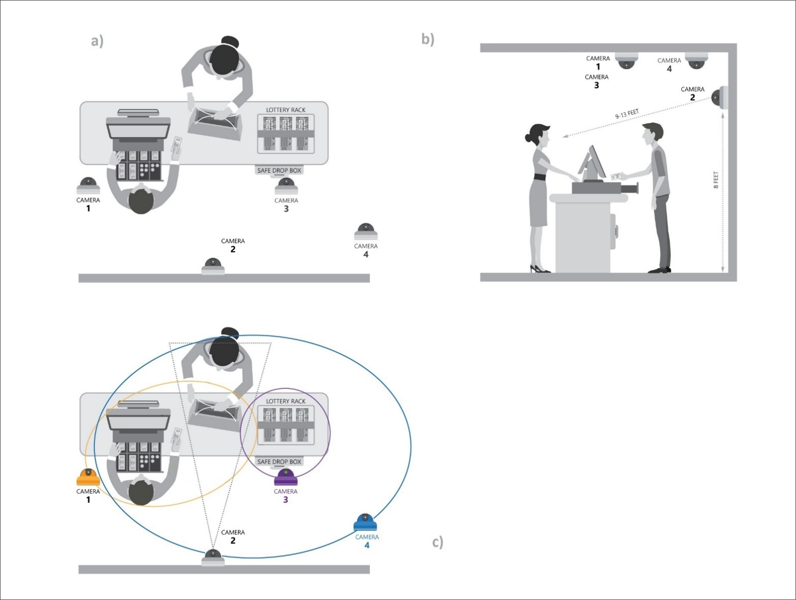
Cameras at the location must be set up in the following way:
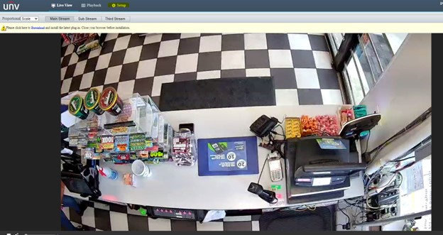
- Camera 1: Counter and drawer close up to see the product name and cash value. The pop view of the counter to be able to generate motion events in cases when a cashier does not use the register for customer’s purchase.
The cash register camera must be mounted on the ceiling and should be aligned with the cash drawer and must see the entire drawer when open. The camera must also see products scanned by the register, and the counter. An optimal distance between the register and camera is 6-7 feet.
- Camera 2: Customer’s face, automatic WB balance, close shot, the cashier should not block the view. This camera should help detect customers’ age clearly.
The customer view camera must be installed on the wall approximately 8 feet above the floor, 2-3 feet aside from the cash register. For an optimal view of a customer, the distance between the camera and object must not be less than 9 ft. The best view is achieved in the range of 9’ and 13’.
- Camera 3: Lottery, instant tickets. An unobstructed view of the instant lottery rack to see the ticket type sold. The motion detection. This setup uses a 12 mm fixed zoom camera.
- In case of lottery rack use:
For instant lottery racks with 4 slots wide and 5 slots high, the camera is mounted on the ceiling above the lottery rack. Position the camera 1 or 2 feet in front of the rack to be able to see the rack in angle. For an optimal view, the height range between the object and camera is 4'-5.5'. For wider lottery racks, you might need to use a 6 mm or 4 mm camera.
- In case of a close counter view:
Mount the camera on the ceiling right above the spot on the counter where products and money are mostly placed. An optimal height is 7 feet above the counter.
- Camera 4: Generic view of cashier’s area to be able to see cash drops and other activities out of close proximity to covered areas.
Mount the camera on the ceiling. Choose a sweet spot based on your store layout. You must be able to see a cashier working on transaction, a customer standing in front of the register and the safe drop box (if present) simultaneously. There is no strict guideline for the camera 4 installation location because every store is unique.
Cameras Installation and Activation
To install and activate cameras at the location, you need to perform the following activities:
- Make a survey and planning.
- Prepare wires.
- Install cameras.
- Connect the PoE switch.
- Activate cameras. Typically, cameras are activated automatically. If not, you can activate them manually. For details, see FAQs: Loss Prevention Analytics > Installation and Configuration.
- Adjust the cameras view.
- Set up the video quality.
Making a Survey and Planning
Before you install and activate cameras at the location, make the following survey:
- Determine where cameras are going to be installed in accordance with your needs. For more details, see Cameras View and Positions.
- Measure the length of the cable from the place where the PoE switch and DC Box will be installed to the spot of each camera. Consider the obstacles that need to be bypassed.
- After the measurement is done, allow 2 feet of slack at the end for play.
Preparing Wires
To prepare wires for cameras:
- Cut the necessary length of the STP CAT5e cable and pull it above the ceiling.
- Crimp both ends of cables to plug them to cameras and the PoE switch. If you use a rack, crimp only one end in accordance with the 568B standard, and second end of the cables punch to the patch panel using the “B” pattern as a reference.
- Fasten the patch panel to the top position of the rack using M6-1.0 bolts.
- Check cable ends for miswiring using the tester.
Installing Cameras
To install cameras:
- Put template stickers that come with a camera on the desired spots.
- Drill the holes using a bit that matches the anchor diameter and then insert anchors into these holes.
- Unmount the camera cover using the hex key that comes with your camera.
- Align the holes of camera housing and drilled holes.
- Plug the CAT5e end to the camera, fasten the screws and then secure camera on the ceiling or wall.
- Leave the camera cover open.
Connecting the PoE Switch
To connect the PoE switch:
- Plug the CAT5e cables from cameras to the PoE switch ports as shown below.
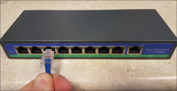
- For the patch panel and rack scenario, use 1 or 2 ft premade CAT5e cables. Plug one end of the cable to the patch panel and the other end to the PoE switch. From “up link” port, pull the cable to the ISP router.

The solid light on the ports means the connection is up. The blinking light means activity (data travels back and forth).
Adjusting Cameras View
To adjust the cameras view:
- After you validate that the camera is functioning properly, make the necessary adjustments by turning and twisting the camera head.
- Once an adjustment is done, fasten the camera cover back.
Setting up the Video Quality
I. To set up the video quality for UNV camera, follow these steps.
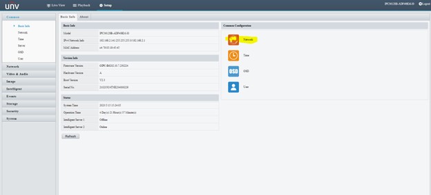
Step 1. Log in the UNV camera user interface using a user name and password information, as follows:
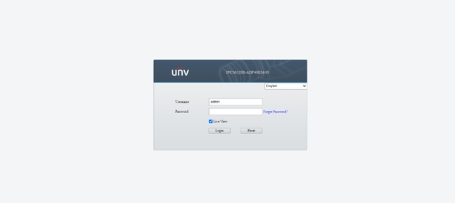
- user name - admin
- password - 123456 (by default or a valid user password)
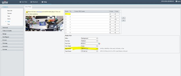
Step 2. Click on Setup menu
Step 3. Click on Network and choose a static IP address for the network connection
Step 4. Type in a static IP address of your network connection in IP Address text field and click on Save button
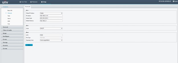
Note. A static IP address is usually provided by your local ISP (Internet Service Provider) for extra charge. Please, contact your ISP office via Email or over the phone to obtain your static IP address.
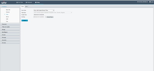
Step 5. Choose your time zone and click on Save button
Step 6. Choose OSD section on the left pane, specify the date format like MM.DD.yyyy and tick off the check box 1
Step 7. To proceed to the video settings, click on Video & Audio
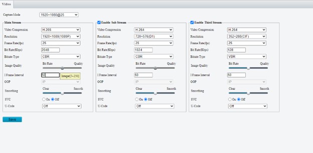
By default, the video compression rate is set to H.265. You should change these settings and tune them up to H.264.
You should also change another video settings following this pattern:
- video frame resolution from 1920 x 1080 (1080 px) to 1280 x 720 (720 px)
- frame rate from 25 to 15 fps
- bit rate from 2048 to 1024 Kbps
- frame Interval from 50 to 20 ms
Step 8. Click on Save button to complete the video quality for UNV camera.
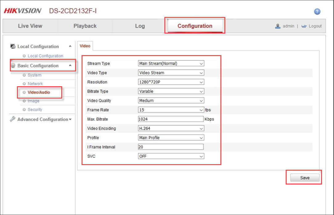
II. To set up the video quality for a HIKVISION camera:
- Click the Configuration tab.
- In the Basic Configuration menu, select Video/Audio.
- On the Video tab, specify these settings:
- from the Resolution list, select 1280 x 720 px.
- from the Frame Rate list, select 15 fps.
- in the Max. Bitrate field, enter 1024 Kbps.
- from the Video Encoding list, select H.264.
- in the I Frame Interval field, enter 20.
- Click Save.